Working of the TCP/IP Layers during a Network Flow
We already know that there are 5 layers in the TCP/IP model : Application Layer, Transport Layer, Network Layer, Datalink Layer, Physical Layer. In this article, I will be explaining what actually happens behind the scenes through these layers as a packet flows from one network to another.

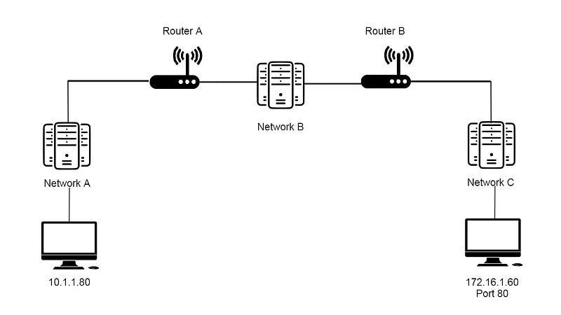
Let us Consider 3 Networks, A, B and C.The above diagram depicts how the 3 networks are connected through 2 routers.
Consider the Computer on Network A as the Client and the one Network B as the Server. The Server(172.16.1.60) is listening on port 80 for incoming connections.
Network A
Application Layer
Now, let’s see what happens if the Client opens the browser and types the address — 172.16.1.60:80 in the address bar. Now the browser communicates with local networking stack (handles networking functions). The networks stack checks its subnet and sees that the destination lives on another network(Network C). Now Computer 1 knows it has to forward the data to the gateway(Router A) on the network.
The Client computer checks the ARP table of the network to determine the Mac Address of the Router A. It finds out that there is no entry. So, it broadcasts an ARP message on the network, which is received by every node on the network. When Router A receives the ARP request, it responds with its MAC address. Now the Computer knows it has to make a TCP connection using an outbound port. So the computer assigns an ephemeral port(used for outbound connections), whichever is available(consider 60000). Now a socket is opened connecting the Web browser to this port.
Transport Layer
Now a TCP segment is constructed by the networking stack at the Transport Layer. All the appropriate fields(source port:60000 and destination port:80) are filled in the header.A SYN flag is set to initiate a 3-way Handshake and a checksum value is calculated.This segment is passed to the Network layer of the stack.
Network Layer
Now this layer constructs an IP Datagram, which includes the Source IP and the Destination IP(Server) and a TTL value of 64. The TCP segment calculated in the Transport Layer is inserted into the payload section of the IP Datagram and a checksum is calculated for the whole. Now this has to be sent to our network’s gateway, whose MAC address is known. So an Ethernet Frame has to be constructed.
Datalink Layer
An Ethernet Frame is constructed with Source(Client) and Destination(Router A) Mac Addresses. The IP Datagram constructed above is inserted into the payload section of the Ethernet Frame and another checksum is calculated. Now this has to be sent across the Physical Layer.
Physical Layer
Now, the network interface sends this binary data in the form of Voltage of an electric current across the CAT6 cable connected between it and switch. The Switch on the network receives this Packet and forwards it to the corresponding MAC address(Router A) in the Packet.
Network B
Datalink Layer
Now Router A receives the frame intended for itself. It calculates the checksum and compares it with the one in the Frame Header, to make sure the data hasn’t been lost or tampered with. It then strips away the Ethernet Frame, leaving just the IP Datagram.
Network Layer
Again checksum verification is performed here.Now it verifies the Destination IP(Server) and performs a quick lookup in the Routing Table. It sees that the quickest way to get to the Network C is via one hop away via Router B. Now Router A a new IP datagram intended for Router B using this data. It decrements the ttl value by 1 and calculates a new checksum value.
Network C
Datalink Layer
Router A looks into the ARP Table and finds an entry for Router B. It constructs an Ethernet Frame with the source as MAC address of its interface on Network B and the destination as that of Router B.The Frame is now sent across Network B to Router B.
Just like before, Router B performs the checksum checks, removes the Ethernet Frame and performs the same on IP Datagram. Now it finds out that the destination is on a locally connected network. So it finally creates a new IP datagram which is encapsulated by a new Ethernet Frame.
Physical Layer
Now this frame is forwarded to the Server(destination) on the Network.
Datalink Layer
The Server receives this frame and identifies its own MAC address. Now it strips away the Ethernet Frame and sees that its own IP address in the IP datagram.
Network Layer
Since there is no need to send to another IP on the network, it strips away the IP datagram, leaving with just the TCP segment.
Transport Layer
Now the Server computer finds out that the destination port is 80. The networking stack checks if there is any such port and finds out that port 80 is currently listening for incoming connections. Now it sees that the SYN Flag is set. Now it notes the Sequence number to put it in the Acknowledgement field.
We are not done yet!
After these many steps, all we have done is just sent a single TCP segment containing a SYN flag from the Client to the Server.Now everything will have to happen again. The Server will respond back with a SYN-ACK flag to Computer 1. Again the Client will respond with an ACK Flag to the Server to complete 3-way handshake. Now the connection has been is established and both the Server and Client can start communicating in a similar fashion.
This is how all the 5 layers of our TCP/IP networking model work together in order to deliver information from one end to the other.
Thankyou for reading so far. Hope you liked it!